The Embedded Stack for Robotics: A Practical Hierarchy from 8-bit AVR to Linux Companion Computers
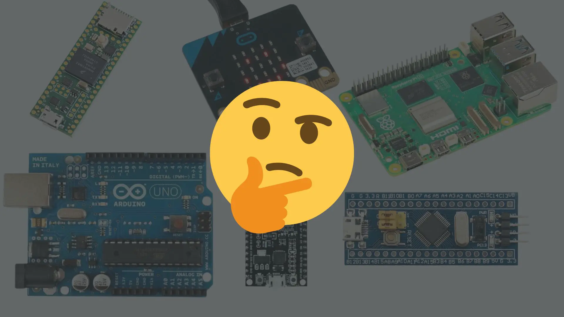
Every robotics project eventually forces the same question: which processor do I actually need? Browse any forum and you will find answers anchored to brand loyalty — “just use an Arduino,” or “Raspberry Pi can do everything.” Neither statement is useful. The real answer is architectural: your hardware selection must be driven by the physical constraints and real-time deadlines of the robot itself, not by what the YouTuber in the thumbnail used.
A line-following robot that needs to react to a sensor edge in 2 ms has completely different demands than a quadcopter that needs to close an attitude control loop at 4 kHz, which is again different from an autonomous drone running stereo-vision-based obstacle avoidance. These are not points on a difficulty slider — they are categorically distinct problems that demand categorically distinct hardware.
This post is a practical map of that hierarchy, built from experience across all four tiers: from building an ESP32-based line-follower as a personal project, to writing bare-metal quaternion EKFs on a Teensy 4.0, to pairing a Pixhawk with a Raspberry Pi 4B for MAVLink-driven autonomous landing.
Tier 1 — 8-bit / 16-bit: Basic Logic and I/O (AVR, Arduino)
Representative hardware: ATmega328P (Arduino Uno/Nano), ATmega2560 (Mega), ATtiny series, BBC micro:bit (nRF51/nRF52, Cortex-M0/M4).
Clock speed: 8–20 MHz. Data bus: 8-bit. FPU: None.
This is where most robotics education begins, and for good reason. The AVR architecture is transparent — there are no caches, no branch predictors, no out-of-order execution to reason about. You write code, it runs in a predictable cycle count, and you can trace a GPIO toggle back to a single assembly instruction. That predictability makes it an excellent learning environment.
Where It Works: Line-Following Robots
For a personal line-following robot project, I built the controller around an ESP32 DevKit — technically overkill for the task, but that is exactly the point. The algorithmic demands of a line-follower sit squarely in Tier 1 territory regardless of what chip you use. The core loop was this:
- Read 8 IR sensors via digital GPIO
- Compute a weighted centroid error (an integer calculation)
- Apply a proportional-derivative correction to two DC motors via PWM
- Loop, repeat
The entire control loop ran in under 200 µs, comfortably within even an 8-bit AVR’s limits. No floating-point was needed — the error was an integer from −100 to +100, the gains were fixed-point scaled integers, and the PWM output was a simple analogWrite. An ATmega328P could handle this without breaking a sweat; the ESP32 was loafing. The lesson is that for control problems this simple, the processor choice is almost irrelevant — which is exactly how you know you are in Tier 1.
⚙️ Why Integer Math Matters on AVR The ATmega328P has no hardware Floating-Point Unit (FPU). A single 32-bit float multiplication requires a software library call that can cost 40–90 clock cycles. At 16 MHz, that is 2.5–5.6 µs — per multiply. A basic complementary filter with 6 float operations per loop iteration can consume ~30 µs just in math. For a 100 Hz control loop this is tolerable; for a 4 kHz flight controller loop, it is a complete non-starter.
Where It Fails
The moment your algorithm needs to do real math — sensor fusion, PID in floating point, kalman filtering, or any trigonometric operation — the 8-bit tier collapses. sin() and cos() on an AVR are expensive software routines. atan2() for heading computation from a magnetometer is painful. Storing attitude as a quaternion and integrating gyroscope rates into it in a tight loop is effectively impossible at useful update rates.
The upgrade trigger: If your algorithm requires floating-point sensor fusion at more than ~50 Hz, or if you need DMA, hardware timers beyond simple PWM, or USB-serial at real bandwidth — move to Tier 2.
The ESP32: The Board That Blurs the Line
No discussion of this tier is complete without addressing the elephant in the room. The ESP32 (Espressif’s dual-core Xtensa LX6 at 240 MHz) is arguably the most popular development board in the hobby and maker space today, and it does not fit cleanly into Tier 1 or Tier 2. It has a hardware FPU, 520 kB of SRAM, built-in WiFi and Bluetooth, and enough compute to run a complementary filter or a simple PID loop comfortably — capabilities that place it well above an ATmega.
But it is not a Cortex-M7. It lacks the tightly-coupled memory, the deep DMA engine, and the deterministic interrupt latency that make a Teensy 4.0 viable for a 4 kHz flight control loop. FreeRTOS runs under the hood by default (the ESP-IDF is built on it), which gives you multitasking but adds context-switch jitter that bare-metal Cortex-M code avoids.
Where the ESP32 excels in robotics: WiFi-connected rovers, Bluetooth RC cars, IoT sensor nodes that do light motor control, and — as in my line-follower above — any robot where the control problem is simple but you want wireless telemetry, OTA updates, or a web-based dashboard for free. The dual-core architecture also lets you dedicate one core to WiFi/BT housekeeping and the other to your control loop, which is a genuine advantage no AVR or even most STM32 boards offer at this price point.
Where it falls short: Hard real-time tasks above ~1 kHz, anything requiring deterministic sub-microsecond interrupt latency, or applications where you need every peripheral (SPI, I2C, UART, timers) running simultaneously with DMA. For those, you are in Tier 2 territory.
📡 Worthy Mentions at This Level The ESP32 is the most prominent, but it is not the only board straddling Tier 1 and Tier 2. The ESP32-S3 adds vector instructions for basic ML inference. The RP2040 (Raspberry Pi Pico) offers dual Cortex-M0+ cores with PIO state machines — a unique architecture for bit-banging custom protocols. The BBC micro:bit V2 (nRF52833, Cortex-M4 with FPU) is an excellent educational platform that punches above its weight for simple sensor-driven robots. None of these replace a Cortex-M7 for serious flight control, but all of them are vastly more capable than an ATmega for projects that need a bit more than basic GPIO and PWM.
Tier 2 — 32-bit Bare-Metal: Real-Time Control (Teensy 4.0, STM32)
Representative hardware: Teensy 4.0 (NXP i.MX RT1062, Cortex-M7), STM32F4/F7/H7 series (Cortex-M4/M7).
Clock speed: 168 MHz – 600 MHz. FPU: Yes, hardware double-precision on Cortex-M7. Architecture: 32-bit, Harvard-variant, deep pipeline.
This tier is where robotics gets serious. The Cortex-M7 core inside the Teensy 4.0 operates at 600 MHz and includes a double-precision FPU, a 16 kB instruction cache, a 16 kB data cache, and a tightly-coupled memory (TCM) interface that gives zero-wait-state access to critical data. The architectural difference over AVR is not marginal — it is several orders of magnitude in raw compute throughput.
TeensyPilot: A Bare-Metal Quadcopter Stack
This is the context where I understand Tier 2 hardware most intimately. TeensyPilot is a custom flight control stack written from scratch in C++ on the Teensy 4.0, targeting DJI-grade stable manual flight as a first milestone before moving toward autonomous hover using stereo cameras.
The core requirements that made the Teensy 4.0 the correct choice:
1. IMU Pipeline Timing
The ICM-20948 IMU is configured in SPI mode with its data-ready signal driving a hardware interrupt on the Teensy. The interrupt handler fires at 8 kHz, reads raw 16-bit gyroscope and accelerometer data via DMA-backed SPI, and timestamps the sample in the TCM. This is only viable because the Cortex-M7’s interrupt latency is deterministic and the DMA engine offloads the bus transaction entirely from the CPU. On an AVR running SPI at 8 MHz, the CPU would be bit-banging or polling through every byte.
2. Quaternion-Based EKF
Attitude estimation uses a quaternion-state Extended Kalman Filter. The predict step integrates gyroscope rates using the quaternion kinematics equation:
// Quaternion derivative from body-rate gyroscope vector (omega)
// q_dot = 0.5 * q ⊗ [0, omega]
Quaternion omega_quat = {0.0f, gyro.x, gyro.y, gyro.z};
q_dot = 0.5f * q * omega_quat;
q = (q + q_dot * dt).normalized();
The update step fuses accelerometer gravity measurement to correct pitch/roll drift. Each call to normalize() requires a reciprocal square root — on the Cortex-M7 FPU, this is a single VSQRT instruction followed by a reciprocal, completing in approximately 14 clock cycles. On an AVR, the equivalent software routine is hundreds of cycles. At a 4 kHz loop rate, this difference is the boundary between a working flight controller and a non-functional one.
3. Cascaded PID Architecture
The flight controller runs a two-stage cascaded PID: an outer attitude loop (setpoint is desired roll/pitch/yaw angle from the RC receiver) and an inner rate loop (setpoint is the angular rate commanded by the attitude loop). The inner rate loop closes at 4 kHz. For the derivative term, the derivative is computed on the measurement, not the error, to suppress derivative kick from setpoint steps:
// Anti-derivative-kick: differentiate measurement, not error
float derivative = -(measurement - prev_measurement) / dt;
float output = kp * error + ki * integral + kd * derivative;
prev_measurement = measurement;
At 600 MHz, running both PID stages, the EKF predict step, motor mixing (Quad-X layout), and DShot signal generation for four ESCs still leaves the processor at well under 50% utilisation on the 4 kHz tick.
⚡ Bare-Metal vs. RTOS at This Tier At 600 MHz on a Cortex-M7, a cooperative bare-metal superloop or interrupt-driven architecture is often more deterministic than a preemptive RTOS for hard real-time tasks. An RTOS introduces context-switch overhead (~1–5 µs per switch), priority inversion risk, and stack memory per thread. For a single-purpose flight controller where every task’s deadline is known and fixed, bare-metal with hardware timer interrupts gives tighter worst-case latency. Add an RTOS when your task graph becomes complex enough that manual scheduling is error-prone — not before.
STM32: The Industry Workhorse
The STM32F4 and F7 series are the MCUs behind most open-source flight controllers (Betaflight, iNAV, early ArduPilot targets). The F405 at 168 MHz was the de-facto standard for years. The H7 at 480 MHz with an L1 cache brought it closer to Teensy 4.0 territory. The ecosystem benefit of STM32 is broad: STM32CubeIDE, HAL libraries, and a massive community of flight controller hardware designs to reference.
For robotic arms and mobile rovers at this tier: STM32 is the pragmatic pick. A 6-DOF arm with trajectory interpolation, inverse kinematics, and servo/stepper control benefits from hardware timers for step generation and the FPU for the trigonometry in IK. The F446 at 180 MHz with its DMA, CAN bus peripheral, and SPI/I2C handles a multi-joint servo drive comfortably.
Tier 3 — Dedicated Flight Controllers: The UAV Standard (Pixhawk)
Representative hardware: Pixhawk 6C, Cube Orange+, Holybro Kakute H7.
Architecture: Dedicated flight controller SoC (typically STM32H7 main + STM32F4/F7 IO coprocessor), with mission-specific PCB design.
This tier is often misunderstood. A Pixhawk running ArduPilot or PX4 is not simply a “more powerful STM32 board” — it is a systems engineering decision baked into hardware. When you use a Pixhawk for a mapping drone or a standard autonomous mission, you are not just buying a chip; you are buying:
What Dedicated Flight Controllers Actually Provide
Isolated power architecture: The main processor, the servo rail, and the GPS/telemetry bus all have separate power domains. A servo current spike does not corrupt your IMU data or brown out your FMU. On a DIY PCB, replicating this requires careful power plane design, LC filters, and LDO regulators on every rail.
Redundant IMU ensemble: The Cube Orange+ has three independent IMUs (ICM-42688-P, ICM-20649, ICM-45686) on thermally isolated mounts, processed by ArduPilot’s sensor voting logic. If one IMU diverges, the EKF automatically deweights it. No custom flight controller build replicates this without significant extra hardware effort.
Vibration-isolated IMU mount: The Cube form factor isolates the FMU board from the carrier board using silicone grommets. Propeller vibration between 80–300 Hz is one of the primary enemies of accelerometer-based altitude estimation. Hardware isolation before software filtering is always preferable.
Flight-proven ArduPilot/PX4 stacks: Thousands of real-world flight hours across thousands of vehicles. The EKF3 in ArduPilot handles GPS denial, optical flow fallback, barometer weighting, and magnetometer calibration through a battle-tested implementation. Reproducing this from scratch is months of work minimum.
⚠️ When NOT to Use a Pixhawk Pixhawk is overkill for a ground rover doing simple waypoint following, for any robot that doesn’t need redundant IMUs, or for any application where you need tight custom control loops that ArduPilot/PX4 doesn’t expose. The overhead of MAVLink and ArduPilot’s scheduler adds latency between your command and motor output that a bare-metal Teensy doesn’t have. Pick Pixhawk when reliability, regulatory compliance, and mission-proven software matter. Pick Teensy/STM32 when you need raw determinism and full-stack ownership.
Tier 4 — Companion Computers: Vision and Autonomy (Raspberry Pi 4B)
Representative hardware: Raspberry Pi 4B (Cortex-A72, 1.5–1.8 GHz), Banana Pi M2 Zero, Jetson Nano/Orin, Intel NUC, Khadas VIM4.
Architecture: Application processor — runs a full Linux OS (Raspberry Pi OS, Ubuntu), has an MMU, virtual memory, a GPU (VideoCore VI on Pi 4B), and gigabytes of RAM.
This is where the most important architectural boundary in robotics exists, and it is the one most beginners get wrong.
Microprocessor vs. Microcontroller: The Fundamental Split
A Raspberry Pi is not a microcontroller. It is a full application processor running a non-real-time operating system. Linux is a time-sharing OS — it schedules processes and can preempt your code at any moment to handle an interrupt, a network packet, a filesystem event, or another process’s slice. The read() call you made to your UART might return immediately, or Linux might schedule your process out for 50 ms while it handles something else. You cannot guarantee timing.
A Cortex-M7 on the Teensy with a hardware timer interrupt firing at 4 kHz will fire at 4 kHz. Linux on a Pi might handle a 4 kHz timer, or it might miss a few while the kernel does something else.
This is why companion computers never directly control motors. They handle the tasks where real-time guarantees are not required but raw compute throughput is — computer vision, SLAM, path planning, and ML inference. The companion computer sends high-level setpoints over a protocol like MAVLink; the flight controller executes them in hard real-time.
When to Go Beyond the Pi: Jetson and NPU-Based Boards
The Raspberry Pi 4B’s VideoCore VI GPU is not designed for ML inference. For tasks like stereo depth estimation, YOLOv8 object detection, or any inference at real-time frame rates, the Jetson Nano (128-core Maxwell GPU) or Jetson Orin (1024-core Ampere + dedicated DLA) are the correct choices. The architectural split with the flight controller remains identical — only the compute substrate changes. The Waveshare IMX219-83 stereo module (which drives the stereo vision work in TeensyPilot’s roadmap) feeds into a Jetson running a depth estimation network, with resulting position data flowing down to the flight controller via MAVLink.
How to Choose: A Decision Framework
Rather than a lookup table, apply these questions in order:
1. Does your control loop need sub-millisecond, guaranteed timing? Yes → You need a microcontroller (Tier 2 minimum). A Linux SBC cannot provide this.
2. Does your algorithm require floating-point math above ~50 Hz? Yes → Move from AVR (Tier 1) to Cortex-M4/M7 (Tier 2). The FPU is not optional.
3. Is your platform an aerial vehicle where reliability directly affects crash risk? Yes → Seriously evaluate Tier 3 (Pixhawk). Redundant IMUs, isolated power rails, and battle-tested EKF implementations are not premature optimization; they are safety margins.
4. Does your robot need computer vision, a full navigation stack, or ML inference? Yes → Add a companion computer (Tier 4). But always keep it architecturally separated from real-time motor control. The companion computer sends setpoints; the microcontroller executes them.
5. Are you building from scratch to learn the full stack? Start at Tier 2. An ATmega teaches you peripherals; a Cortex-M7 teaches you everything that matters in production: DMA, interrupt latency, cache coherency, and what happens when your filter diverges at 600 MHz. TeensyPilot exists precisely because building a flight controller from scratch on a Teensy 4.0 teaches you more about embedded systems in six months than five years of Arduino projects.
The hardware is not the project. It is the constraint that shapes the project. Understanding why each tier exists — the FPU boundary, the real-time OS boundary, the power isolation boundary — is what separates an engineer who picks the right tool from one who fights the wrong one for months. Start simple, push it to its limit, feel where it breaks, and then step up with a reason.
That reason is always physics, never preference.