Case Study
Automated 6-Axis IMU Calibration Rig
Engineered a dual-stepper automated tumbling rig to perform precise 6-point accelerometer and gyroscope calibration for TeensyPilot, solving a severe cantilever torque problem through iterative counter-weighting and validating the results against a hand-calibration AHRS baseline.
The Challenge
Flawless autonomous flight starts with flawless IMU offsets. Manually calibrating a flight controller by hand-holding it against a desk edge introduces exactly the errors you’re trying to eliminate — inconsistent angles, micro-vibration, and human timing. The goal was a rig that could lock a board into all six standard calibration orientations (+Z, −Z, +X, −X, +Y, −Y) automatically and repeatably, then validate the result against real AHRS output.
The catch: suspending a motorized U-beam and a flight-controller sled in mid-air on a single shaft creates a large cantilevered load. Local sourcing constraints ruled out the obvious fixes — no metal motor flanges, no silent TMC drivers — so every problem had to be solved mechanically or in firmware with whatever was available on the bench.
Technical Deep Dive
Mechanical Design: From Failure to Final Solution
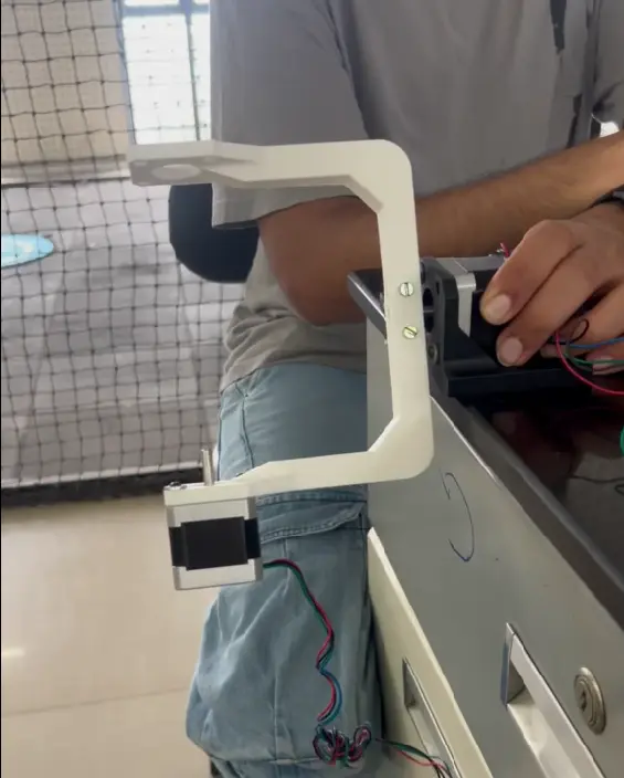
Stage 1 — It didn’t work. The first assembled version made the problem immediately visible. The U-beam, tilt motor, and calibration sled hanging off the base shaft created a cantilever that consumed over 65% of the base NEMA 17’s holding torque just fighting gravity. The result was shaft sag, slip at the coupling, and missed steps on the first 90° sweep. The rig looked right on paper and failed on the bench within thirty seconds.
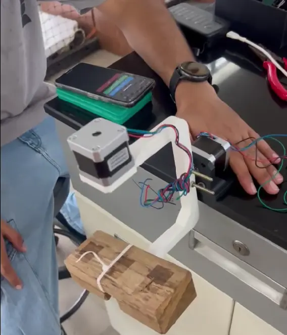
Stage 2 — Proof of concept with a spare mass. Before ordering parts or redesigning anything, a spare steel mass was bolted to the opposite arm of the U-beam. The sag disappeared immediately. The base motor could complete a full rotation without stalling, the shaft stopped slipping, and the motion became smooth. That single test confirmed the root cause: the problem was load balance, not stepper sizing. The center of mass needed to sit on the shaft axis, not 12 cm off it.
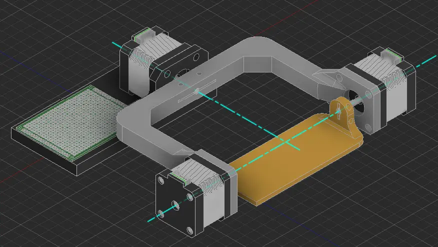
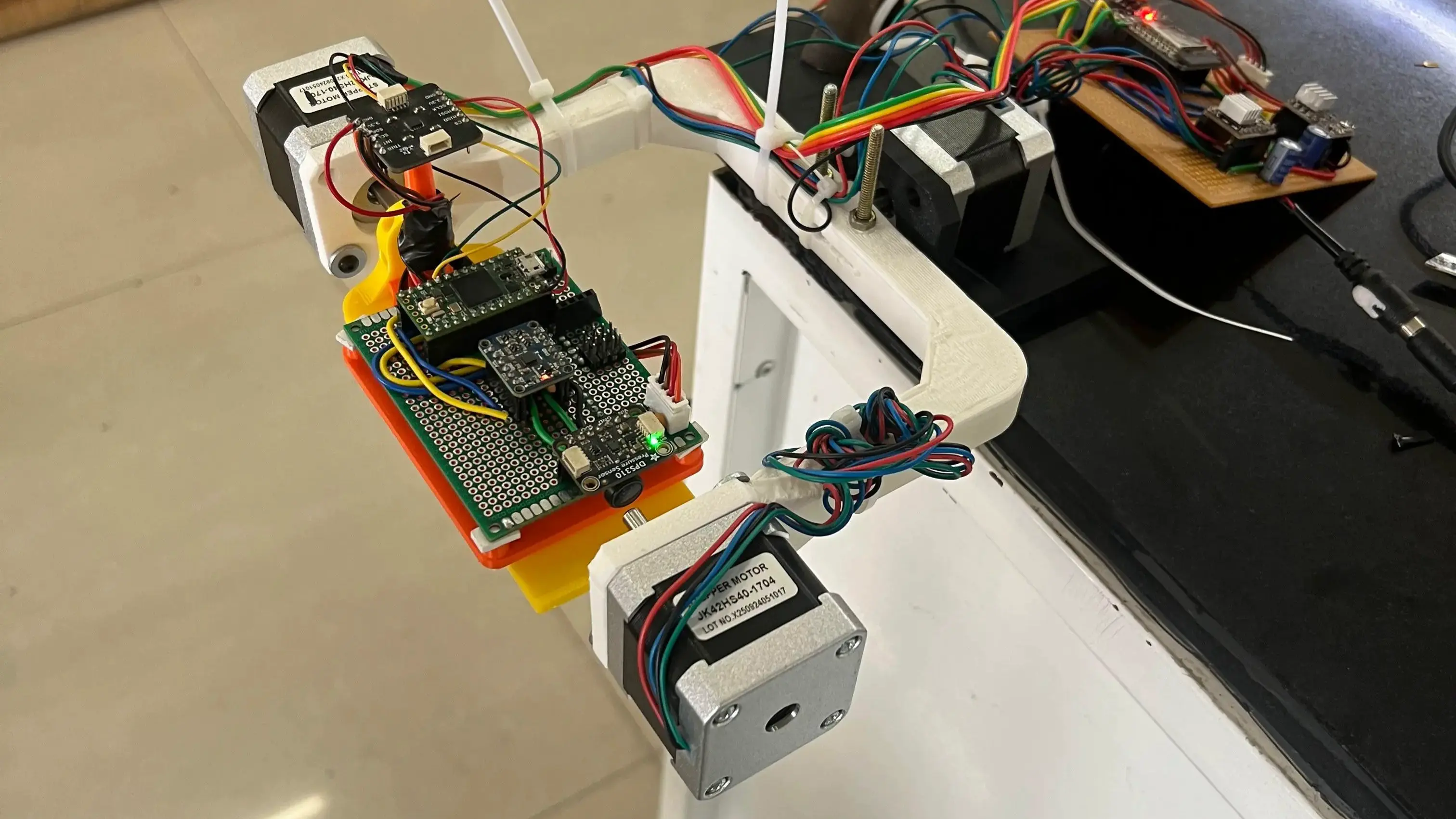
Stage 3 — Final design with a second NEMA 17. The crude steel mass proved the principle but sat too far from the shaft and wasn’t adjustable. The final version replaced it with an unpowered NEMA 17 mounted symmetrically on the opposite arm. Its position along the beam is slideable, making the balance tuneable. The assembly became visually symmetric, mechanically stable, and repeatable enough for precision calibration work.
Two additional mechanical fixes made the design production-viable under local sourcing constraints:
- C-Clamp Hub: With 5 mm metal motor flanges unavailable, a straight PLA press-fit slipped under dynamic torque. The fix was a custom Fusion 360 hub with a stress-relief slit through the 5.2 mm bore and a perpendicular M3 pinch bolt — the hub clamps onto the shaft rather than relying on friction alone.
- Print Orientation for Load Path: The U-beam was sliced flat on its back on the A1 Mini rather than upright, aligning the continuous FDM perimeter walls with the primary bending moment instead of across the layer lines — the difference between an arm that flexes and one that snaps.
Electronics & Firmware Architecture
- Standalone Wireless Control: Rather than fight university Wi-Fi or tether to a laptop, the ESP32 runs as its own access point (
TeensyPilot_Rig) hosting a dark-mode HTML dashboard. A phone connects directly and triggers calibration sequences over HTTP with no laptop in the loop. - Non-Blocking Stepper Loop: Blocking
runToPosition()calls would freeze the controller mid-sequence. The firmware drives both DRV8825s from a non-blockingrun()loop, pulsing at up to 8,000 steps/sec while still servicing incoming HTTP requests. - Driver Tuning Without TMC Silence: With silent TMC2209 drivers unavailable, the DRV8825s were hardwired to 1/32 microstepping to smooth the motion profile. The supply was upgraded from 12V 2A to 12V 5A so VREF could be pushed to 0.60 V — roughly 1.2 A of holding current per motor — keeping the sled dead-still while 1g baseline readings are captured.
The 6-point sequence is a flat lookup table walked with a 5-second settle delay at each stop, letting mechanical resonance die out before the offset is recorded:
Position POSITIONS[6] = {
  {  90.0f, 0.0f },  // 1: X+ face up  (= -X down)
  {  -90.0f,  0.0f },  // 2: X- face up  (= +X down)
  {  0.0f,   -90.0f },  // 3: Y+ face up  (= -Y down)
  {  0.0f,   90.0f },  // 4: Y- face up  (= +Y down)
  {   0.0f, 180.0f },  // 5: Z+ face up  (= -Z down / upside down)
  {   0.0f,   0.0f },  // 6: Z- face up  (= +Z down / flat normal)
};
The settle delay is not conservative padding — it is the minimum time for the DRV8825’s microstepped motion to damp completely at this inertia. Capturing a reading while the sled is still ringing from the last move reintroduces exactly the vibration the rig was built to eliminate.
Validation: Hand Calibration vs. Machine Calibration
A calibration rig is only as good as the flight data it produces. To close the loop on the project’s core claim, TeensyPilot’s AHRS was run with offsets from two sources: a manual 6-point hand calibration and the automated rig calibration.
Hand Calibration — Holding the board against a desk edge and eyeballing orthogonal alignment introduces small but consistent angular misalignment at every face. After loading these offsets, placing the board flat on the bench showed a persistent steady-state attitude error: the artificial horizon drifted slightly off level even when the physical board was perfectly still. The EKF’s gravity reference was subtly wrong because the calibration positions were subtly wrong.
Machine Calibration — The rig locked each face under motor power with a 5-second vibration-free settle before capture. After loading these offsets, the same bench test showed a significantly smaller steady-state error. The artificial horizon held level with the physical board. The rig’s repeatability and vibration-free settle time translated directly into a tighter sensor fusion solution — which is the entire reason the rig was built.
Results
- Zero Dropped Steps: The counterweight plus the 12V 5A upgrade eliminated all missed-step behavior — both motors handle the dynamic swing of a full 6-point sequence cleanly.
- Validated Accuracy: Machine calibration produced a measurably smaller AHRS steady-state error than hand calibration on the same hardware, confirming that rig precision translates directly into attitude estimation quality.
- Fully Wireless Operation: The mobile dashboard drives the full 6-point sequence, individual axis presets, and homing/e-stop with no perceptible lag and no laptop tether.
- Current Stage: Electronics validated on a perfboard prototype (ESP32 + dual DRV8825) ahead of a dedicated carrier PCB. Mechanical assembly is complete and running repeatable calibration passes on the bench.
Gallery & Models
Click any image to preview.