GPS RTC Backup Power: Why I Replaced the MS621FE Coin Cell with a CPH3225A Supercapacitor
Most GPS module schematics include a backup battery that nobody ever explains. The reference design shows a coin cell, the application note confirms it, and most designers copy it forward without questioning whether it is the right choice for their specific build. I did the same — until I tried to actually source the component in India, read the charging circuit requirements more carefully, and ran the backup duration math for my use case.
The GPS module is a u-blox MAX-M10S-00B, paired with an IST8310 magnetometer for heading, and the whole assembly connects to a companion computer via I2C and UART. The original backup component was a MS621FE — a Seiko Instruments rechargeable lithium coin cell. The replacement is a CPH3225A — a Seiko Instruments SMD electric double-layer capacitor (supercapacitor) in a 3225 package.
This post documents exactly why that swap happened: what the V_BCKP pin actually needs, where the MS621FE falls short for this use case, what the CPH3225A gives up and gains, and how to calculate whether a supercapacitor’s backup window is sufficient before you commit the footprint to layout.
What V_BCKP Actually Does
The MAX-M10S has a dedicated backup supply pin: V_BCKP. When the main VCC rail drops or disappears entirely, the module automatically switches its power source to V_BCKP and enters a low-power backup mode. In this state it draws approximately 15 µA (typical, from the u-blox MAX-M10S datasheet, Table 8) and maintains two things:
- Real-Time Clock (RTC): The module tracks elapsed time even with no satellites visible. When VCC returns, it knows roughly what time it is.
- Satellite data cache: Almanac and ephemeris data for the satellite constellation in view. This is the expensive part — a full ephemeris download from a cold start takes 12–30 seconds and requires continuous satellite visibility. Stored data enables a Hot Start (typically under 1 second to first fix) or Warm Start (a few seconds) on power-up instead.
Without backup power, every power cycle is a Cold Start. On a robot that powers down between runs, gets firmware updates, or has a battery swapped, losing Hot Start capability means losing 15–30 seconds of fix time every single session. For anything that needs position quickly after arming — which is most UAV and rover applications — this is a real operational cost, not an academic one.
The V_BCKP pin on the MAX-M10S must stay between 1.71V and 3.6V during backup mode. The module switches autonomously; no firmware is needed to manage the transition.
Option A: MS621FE Rechargeable Coin Cell
The MS621FE is Seiko’s SMD rechargeable lithium manganese dioxide coin cell, widely used in GPS and RTC backup applications. On paper it is the obvious choice.
Electrical characteristics:
| Parameter | Value |
|---|---|
| Nominal voltage | 3.0V |
| Capacity | 5.5 mAh |
| Max charge voltage | 3.3V |
| Max continuous charge current | 0.1 mA |
| Self-discharge (20°C) | < 1% per year |
| Operating temperature | −20°C to +60°C |
Backup duration with MAX-M10S:
t = Capacity / I_BCKP
t = 5500 µAh / 15 µA
t ≈ 366 hours  ≈  15 days
Fifteen days of backup is genuinely impressive and is why every GPS reference design defaults to it. If a rover sits on a shelf for a week, the MS621FE keeps the RTC and satellite cache alive. That is a real advantage.
The charging circuit:
The MS621FE cannot be connected directly to a 3.3V rail without current limiting. At full discharge (~2.5V), the in-rush current would be:
I = (VCC − V_cell) / R_internal ≈ (3.3 − 2.5) / ~10Ω = 80 mA
That exceeds the maximum charge current by a factor of 800 and would damage or destroy the cell. The correct approach is a series resistor that limits charging current. The schematic uses R2 = 1 kΩ, which limits the maximum charge current to:
I_max = (3.3V − 2.5V) / 1000Ω = 0.8 mA
Still above the MS621FE’s 0.1 mA continuous charge rating, but the actual average charging current is lower because the cell voltage rises as it charges, reducing the differential. In practice a 1 kΩ resistor is acceptable — TI and u-blox reference designs use similar values — but it requires careful review against the specific cell’s datasheet. A blocking diode is also typically added between VCC and the cell to prevent the 3.3V rail from sagging into the coin cell if VCC drops toward cell voltage during a transient.
Where the MS621FE Failed This Design
India sourcing. The MS621FE is not available on Robocraze, Electronicscomp, or most Indian electronics distributors. International ordering from Mouser or DigiKey adds ₹1,500–2,500 in shipping per order and 2–4 weeks lead time. For a one-off prototype board, ordering a single SMD coin cell internationally is a significant overhead relative to its function.
Transport classification. Rechargeable lithium cells — even small ones like the MS621FE — are classified as lithium batteries under IATA DGR. International air shipments require specific packaging and documentation. This is not impossible, but it adds friction to an already slow process.
Overengineered for the use case. Fifteen days of backup is impressive, but my robots don’t sit idle for fifteen days. They sit idle for hours between sessions, or overnight at most. The backup window required is not “two weeks” — it is “long enough to survive a power cycle, a firmware flash, and a battery swap in the same session.” That number is measured in minutes to hours, not days.
Option B: CPH3225A Supercapacitor
The CPH3225A is Seiko’s SMD electric double-layer capacitor (EDLC) in a 3.2 × 2.5 mm package. It is a supercapacitor, not a battery — it stores charge electrostatically rather than through a chemical reaction, which changes both its strengths and its limitations.
Electrical characteristics:
| Parameter | Value |
|---|---|
| Capacitance | 33 mF (0.033 F) |
| Rated voltage | 3.3V |
| ESR (1 kHz) | ≈ 100 Ω |
| Leakage current | < 3 µA at rated voltage |
| Self-discharge | Moderate — see discussion |
| Operating temperature | −25°C to +70°C |
| Package | SMD 3225 (3.2 × 2.5 mm) |
Backup duration with MAX-M10S:
For a capacitor discharging at constant current, backup duration is:
\[t = \frac{C \cdot (V_{\text{start}} - V_{\text{cutoff}})}{I_{\text{BCKP}}}\]Where:
- $C$ = 33 mF = 0.033 F
- $V_{\text{start}}$ = 3.3V (fully charged to rail voltage)
- $V_{\text{cutoff}}$ = 1.71V (MIN V_BCKP per MAX-M10S datasheet)
- $I_{\text{BCKP}}$ = 15 µA = 0.000015 A
58 minutes of backup at the GPS module’s guaranteed minimum V_BCKP threshold. In practice, with the MAX-M10S drawing closer to 15 µA at 3.0V rather than at the absolute minimum, the effective window before the module loses its satellite cache is longer — but 58 minutes is the conservative design number.
The charging circuit:
Unlike the MS621FE, the CPH3225A has no maximum charge voltage concern — it is rated to exactly 3.3V, matching the supply rail. The only charging consideration is the inrush current when V_BCKP is fully discharged. With R2 = 1 kΩ:
I_inrush(max) = (3.3V − 0V) / 1000Ω = 3.3 mA
This is within the CPH3225A’s rated charge current. The RC charge time constant is:
τ = R × C = 1000Ω × 0.033F = 33 seconds
Full charge (≈ 5τ) takes approximately 165 seconds from a completely discharged state. After a normal power cycle — where the cap was only partially discharged — charge time is much shorter.
No blocking diode is strictly necessary between VCC and V_BCKP since the supercapacitor’s rated voltage matches the rail, but a diode is still good practice to prevent V_BCKP from backfilling the main rail during VCC droop.
Head-to-Head Comparison
| Parameter | MS621FE | CPH3225A |
|---|---|---|
| Backup duration | ~15 days | ~58 minutes |
| Charging circuit complexity | Resistor + blocking diode + careful current analysis | Resistor only |
| Rated voltage | 3.0V nominal, 3.3V max charge | 3.3V (matches rail exactly) |
| India availability | Poor — international order required | Good — standard passive, available locally |
| Shipping classification | Lithium battery (IATA DGR) | Standard passive component |
| PCB footprint | Proprietary SMD coin cell pads | Standard 3225 SMD pads |
| Price (local) | Unavailable locally | ~₹40–80 per unit |
| Self-discharge | < 1% / year | Measurable — loses charge over weeks if unpowered |
| Charge time (1kΩ) | ~Hours to full | ~165 seconds (5τ) |
| Component lifetime | ~500 charge cycles | > 100,000 charge cycles |
The lifetime figure is worth noting separately. The CPH3225A has dramatically more charge cycles than any rechargeable coin cell, which matters for a component that charges and discharges every time the board is powered on. A GPS module used in regular development testing could see the MS621FE degrade within a year of daily power cycling.
Schematic: Before and After
The original schematic used the MS621FE directly on the V_BCKP line with R2 (1 kΩ) as the charge-current-limiting resistor:
VCC_3V3 ──── R2(1kΩ) ──┬──── B1(MS621FE+) ──── GND
                        │
                    V_BCKP (MAX-M10S Pin 6)
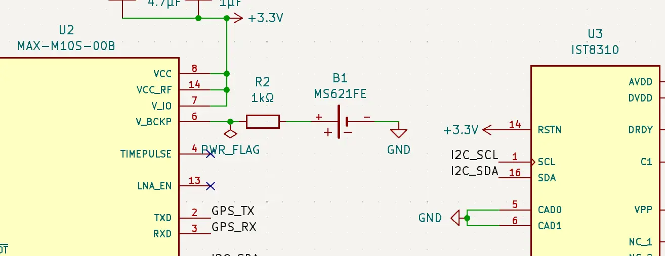
Original design: MS621FE rechargeable coin cell on the V_BCKP line. R2 limits the charge current into the cell.
The replacement substitutes the CPH3225A on the same net with the same R2. The only schematic change is B1’s component reference and footprint — the rest of the circuit is identical:
VCC_3V3 ──── R2(1kΩ) ──┬──── CPH3225A(+) ──── GND
                        │
                    V_BCKP (MAX-M10S Pin 6)
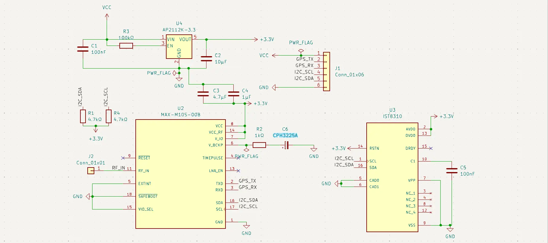
Revised design: CPH3225A supercapacitor on V_BCKP. Schematic is electrically identical to the MS621FE version — only the component reference changes.
This is the key engineering point: the two components are footprint-incompatible but schematically near-identical for this application. The only reason to treat them as a major design change is the backup duration tradeoff — which is a use-case question, not a circuit question.
PCB Footprint: The Practical Difference
The MS621FE uses a two-pad SMD footprint with pad dimensions specific to Seiko’s SM-621FE land pattern specification. It is not a standard library component in KiCad 8.0 — it needs a custom or downloaded footprint.
The CPH3225A uses a standard 3225 SMD capacitor footprint, which is available natively in KiCad’s passive component library. Pad dimensions, courtyard, and silkscreen are all standard. Swapping the footprint in KiCad takes thirty seconds.
For prototype boards where component availability and iteration speed matter more than long-term backup duration, this is a meaningful practical advantage.
Decision Summary
The CPH3225A is the right component for this design for three independent reasons, any one of which would be sufficient:
Sourcing: It is available in India at normal component prices without international shipping, customs delays, or lithium battery transport documentation. The MS621FE is not.
Use-case fit: 58 minutes of backup covers every power-cycling scenario in an active development and field deployment workflow. Fifteen days of backup is solving a problem that doesn’t exist in this build.
Circuit simplicity: The CPH3225A’s rated voltage matches the supply rail exactly, eliminating the charge current analysis that the MS621FE requires. The circuit is simpler, the failure modes are fewer.
The tradeoff given up is the extended backup window — relevant only if the hardware is stored unpowered for more than an hour. For this module, in this build, that scenario doesn’t occur.